

I continued today by positioning the Instrument Panel Attach Flanges (F-1003D & E) simultaneously against the Forward Fuselage Top Skin (F-1071) and the forward side of the Instrument Panel (F-1003A). As I held the attach flanges in place, my Dad match-drilled #40 the holes by using the Forward Fuselage Top Skin as the drill guide. Afterwards I match-drilled #19 through the screw holes in the Instrument Panel (F-1003A) into the Instrument Panel Attach Flanges (F-1003D & E). I then proceeded to remove the Instrument Panel Attach Flanges (F-1003D & E) and then using a nutplate as a drill guide, I match-drilled #40 the two nutplate attach holes for each screw hole. I deburred the holes and edges of the Instrument Panel Attach Flanges before I dimpled the nutplate attach holes and the skin attach holes. Next I machine countersunk the rivet holes in the Hand Hold Doublers and then removed them from the Forward Fuselage Top Skin (F-1071) and deburred the holes and edges. I removed the Forward Fuselage Top Skin (F-1071) from the sub-structure and deburred the holes and edges. I then dimpled all the holes except those that had been marked. I also deburred and dimpled the holes in the flanges of the Firewall Bulkhead (F-1001A) that are common to the Forward Fuselage Top Skin (F-1071). I removed the Instrument Panel subassembly from the Forward Fuselage Ribs (F-1044A & F-1045) and disassembled the Instrument Panel Attach Flanges and Instrument Panel Lower Flange from the Instrument Panel. I deburred all the holes and edges of the Instrument Panel Attach Flanges and then dimpled all the rivet holes as was required. I removed the Sub-Panel / Forward Fuselage Rib Subassembly from the Forward Fuselage, disassembled it into its individual components, and then deburred the holes and edges of all the parts. Finally I dimpled the skin attach rivet holes in the Forward Fuselage Ribs (F-1044A & F-1045), Sub Panel Center (F-1068A), and Sub Panel Sides (F-1068).
Archive for the ‘31-Upper Fwd Fuse Asm’ Category


Today I began attaching the Instrument Panel Lower Flange (F-1003B) and Instrument Panel Attach Flanges (F-1003C) to the Instrument Panel (F-1003A). I positioned the Instrument Panel Attach Flanges (F-1003D & E) over the Instrument Panel and fluted the outboard ends as I needed to match the Instrument Panel upper edge contour. I then attached the Instrument Panel subassembly to the Forward Fuselage Ribs (F-1044A & F-1045) and clecoed the Forward Fuselage Top Skin (F-1071) to the Instrument Panel understructure. Next I had to form the Hand Hold Doublers (F-1071B) to match the contour of the Forward Fuselage Top Skin (F-1071), which created a left and right hand version of the Hand Hold Doublers. I then clecoed the Hand Hold Doublers to the Forward Fuselage Top Skin and final-drilled #40 all the holes that are common between the two parts. I also traced the perimeter of each Hand Hold Doubler so that I know which holes will not be dimpled in the Forward Fuselage Top Skin (F-1071) and final-drilled #40 all the holes in the top skin that are common to the sub-structure.


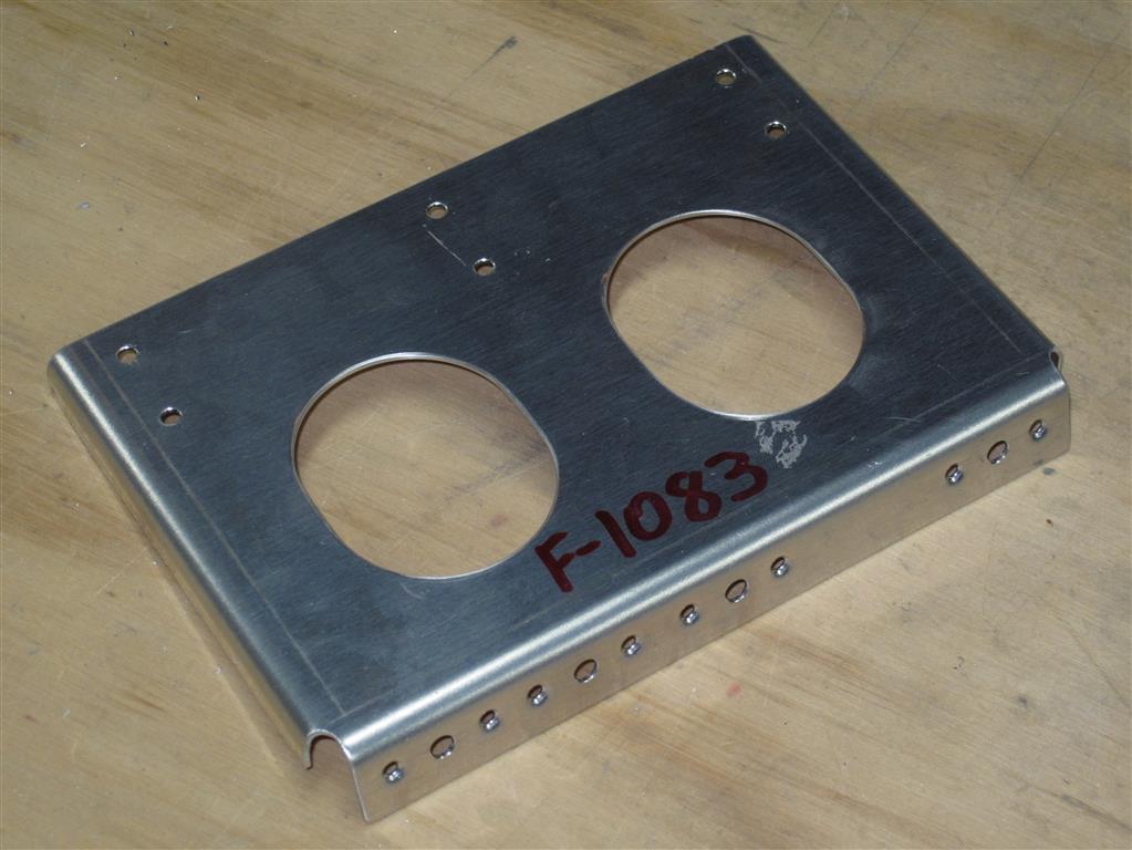
Tonight I began by clecoing the Fwd Fuselage Rib (F-1044A), Angles (F-1044D, E, & F), Fwd Fuselage Ribs (F-1045), Sub Panel Center (F-1068A), Sub Panel Sides (F-1068B), and Control Cable Bracket (F-1083) together. Next I final-drilled #30 all of the common holes in the parts that I had just clecoed together.


Then I inserted the Angle (F-1044B) and Spacer (F-1044C) through the angle shaped opening in the Sub Panel Center (F-1068A) and clecoed the angle and spacer to the Fwd Fuselage Rib (F-1044A). The next step was for me to remove the Control Cable Bracket from the Sub Panel Center (F-1068A) and final-drill the nutplate screw holes (#19) and the nutplate attach holes (#40) in the Control Cable Bracket. Afterwards I deburred and dimpled the Control Cable Bracket as per the instructions.

I began final-drilling #19 all holes in the Instrument Panel (F-1003A) and all nutplate screw holes in the Instrument Panel Lower Flange (F-1003B). Next I machine countersunk the nutplate attach holes and the rivet holes in the Instrument Panel Lower Flange.


Tonight I began fabricating the Spacer (F-1044C), the Angle (F-1044B), and the Inst. Panel Attach Flanges (F-1003D & E) from the material that was specified on the instructions. Next I broke apart the Angle (F-1044DEF) into individual pieces and laid them aside. I then began to flute and straighten the flanges of the Inst. Panel Attach Flange (F-1003C) and cut it apart into individual left and right pieces.


After getting the parts fabricated I was able to move on to the next step and began final-drilling #40 all the nutplate attach holes and #19 all the nutplate screw holes in the Inst. Panel Attach Flange (F-1003C). Afterwards I deburred all the holes and dimpled the nutplates and their attach holes in the Inst. Panel Attach Flange. I was then able to begin final-drilling, deburring, and dimpling all of the required holes in the Fwd Fuselage Ribs (F-1044A & F-1045).


Next I used the edge of my work table and bent the lower portion of the Sub Panel Center (F-1068A) and Sub Panel Sides (F-1068B). Finally I was able to flute and straighten the curved flanges of the Sub Panel Sides (F-1068B) before shutting down for the night.


