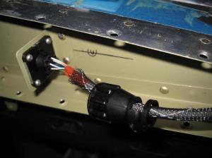
I came home tonight and first removed the Rudder and the Vertical Stbilizer. I then built the CPC connector for the bottom of the rudder that will operate my Rudder Trim.
Archive for the ‘03-Rudder’ Category
Today I started working on the tail light adapter piece by first lining it up to the end of the Lower Rudder Fairing (R-1011). I carefully match-drilled all six holes to 1/8” and clecoed each one as I drilled. I then marked off the diameter of the center hole and drilled out as much as I could before using my dremel tool to finish it up. To set the adapter flush with the fairing, I had to drill a couple of holes so that the threaded holes in the adapter would fit inside. Once I had it all ready, I scuffed up the one side that’s against the fairing and cleaned it with Lacquer Thinner. Then I primed that one side and let it dry. Finally I used the blind rivets that were supplied in the kit and carefully riveted the adapter onto the Lower Rudder Fairing.
I started with the Rudder Bottom Fairing (R-1011) and like before I got it matched and final drilled with the rudder.
However for this part I want to make it removable because I want easy access to my taillight wiring. Therefore I match-drilled the holes, based on K1000-06 nutplates, and countersunk them to accept the dimpled skins and the AN426AD3-4 rivets I will be using. I carefully squeezed all the rivets into the nutplates and then mounted it to the rudder with a few screws (AN507-6R6) to see it all together. Now on to the taillight adapter!!!
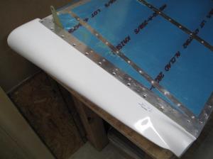
I used a couple of days to work on the fiberglass Elevator Tip Fairings (E-912) and the Rudder Tip Fairing (R-1009). First I removed any interference between the flanges and the Elevator Trailing Edges (E-1023) so that the tips could be fully inserted into the elevators. Then I match drilled them using a #40 drill and clecoed the fairings into the elevator as each hole was drilled. Next I final drilled the holes, starting from the front and working my way back, using a #30 drill. I removed the tips so that I could deburr and dimple the skins and then I countersunk the tips to accept the dimples in the skin. Finally I clecoed it all back together and riveted the Elevator Tip Fairings (E-912) onto the elevator assembly using the CS4-4 blind rivets.
The same basic procedure was used for the Rudder Tip Fairing (R-1009) except that I had to trim a lot off the width of the molded flange before I could get it to fit tightly. Again I matched and final drilled the necessary holes before I deburred, dimpled, and countersunk the parts. Finally I clecoed it all back together and riveted the Rudder Tip Fairing (R-1009) onto the rudder assembly using the CS4-4 blind rivets.
I was able to start today off by final-drilling the leading edge holes with a #30 drill. Afterwards I deburred the holes, clecoed them back together, and riveted them together using AD-41-ABS pull rivets.
Next I clamped the Counterbalance Weight (R-1014) onto the front flanges of the Top Rib (R-1003) and Counterbalance Rib (R-1012). I then match-drilled the two holes in the Counterbalance Weight into the rib flanges using a #19 drill. I secured the weight and slowly folded the skins  around it to create a slight crease. I removed the weight and clecos, and then I clamped the skin (along the crease) between two pieces of wood. I slowly tapped the skin until I had bent it to approximately 85°. I repeated this process for the other side before reinstalling the Counterbalance Weight. After securing the Counterbalance Weight and Skins in place, I proceeded to locate the holes by tapping a #19 drill from the back side of the weight to create a small dimple in the skins. With the dimples I was able to drill two small holes into the skin using a #40 drill. Now I put it all back together and use the drilled skin to match drill the holes into the other using a #30 drill. I then drilled through the holes again but this time with a #19 drill. Disassembled everything again, deburred the holes, and dimpled them for a #8 screw. I put a small bend along the edge of the outside skin and countersunk the holes in the Counterbalance Weight to accept the dimples. That was it for tonight, I’ll finish the Rudder up tomorrow.
Tonight I started rolling up the leading edge of the Rudder Skins. I used a 1” broom handle and I followed the instructions to roll one section at a time starting with the section closest to the Counterbalance Rib (R-1012). That made things a lot easier than trying to do the whole thing at once. I then clecoed the leading edges together and that was enough for tonight.
Now I have reached the part that I have read about on other people’s websites, the “double-flush” rivets in the trailing edge. Previously I took a 6ft piece of angled steel that I had polished on one side to set rivets with and screwed the other side into one of my work tables. I used the Trailing Edge (R-1006) to match-drill some 1/32” holes into the steel so that I could cleco the Rudder down when riveting the “double-flush” rivets. Now I was able to insert a rivet into every other hole on one side (except where my trim tab will be) and tape them down with some rivet tape. I flipped the Rudder over and followed the instructions of setting every tenth rivet about halfway down with my back riveting tool and a 2X rivet gun. This started with first setting the tool parallel to the surface of the angled steel and rotating the tool to be parallel with the surface of the rudder as I riveted. I took my time, but in the end this was a lot easier to do than what I thought it was going to be. I then went back and jumped around to each rivet and set the rest halfway down using the same method.
I did have an issue with a couple of rivets only because I placed them directly over a couple of holes in my angled steel. Needless to say, when I riveted them they did not do so well and therefore I ended up replacing them and this time marking my angled steel bar with a silver sharpie so I know where those holes are and not repeat my mistake.
Afterwards I flipped the Rudder over, checking the straightness of the edge before continuing, and everything looked good. Therefore I clecoed the Rudder down on the angled steel again but this time I switched to my mushroom set and riveted them on the manufactured side of the rivet. This set the shop head side into the dimpled holes pretty well. I repeated the process for the other holes except this time I had the rivets facing the opposite direction. Again I left off the rivets where my trim tab will go and will install them next. After all of the rivets were set I was ready to install the Trim Tab piece. I used the same alternating rivet method, though I was not sure if it would come out the way I wanted it with the countersunk Trim Tab side. I used some AN426AD3-4.5 rivets and they came out perfectly!!! In the end the only thing I found was the 2X rivet gun did not set all the rivets perfectly flush. I switched to my 3X gun and used the mushroom set to tap the rivets a few times on the shop head side. Now they are nice and flush!!!
I came home tonight and started riveting the Skins (R-1001) to the Spar (R-1002) flanges. I had to enlist my Dads help again to rivet the lower rivets together because my rivet squeezer was not able to reach them. Once those where completed I riveted the Counterbalance Rib (R-1012) to the Spar (R-1002) and then the Skins (R-1001). Finally I riveted the Top Rib (R-1003) to the Skins and called it a night.
Now that the tank sealant has cured I removed the clecos from the trailing edge and cleared out the excess sealant. I also trimmed off the sealant that was sticking out past the trailing edge with a razor blade. Next I clecoed the Spar (R-1002) to the Shear Clips (R-1010) and then riveted them together using LP4-3 rivets. I then riveted the Bottom Rib (R-1004), the Horn (R-1005), and the Striker Plates (R-1007) to the Spar (R-1002). Finally I riveted the Top Rib (R-1003) together and then riveted it to the Spar (R-1002). That was enough for tonight.
Finally, tonight was the night to get everything sealed up. My Dad came down and helped me out because there was no way to do this without help. We first started with the Rudder by smearing the sealant on both sides of the Trailing Edge (R-1006). Then we carefully positioned the Skin (R-1001-L) and rolled it back so we could rivet the stiffeners. We slowly moved our way up until all the stiffeners and shear clips were riveted together and the trailing edge clecoed together. We then laid the Rudder on the workbench and put a board and some weight on the trailing edge to hold it flat against the workbench.
We then put tank sealant around the foam ribs for the elevators and placed them between the skins. Next we smeared sealant on both sides of the Trailing Edges (E-1023) and sandwiched them between the skins and clecoed them all into place. Like the Rudder we laid them down on the workbenches and placed some wide boards and weight across the trailing edge to get a good bond.
Next we put tank sealant around the foam ribs and inserted them into the Trim Tab Skins (E-919). Then we slipped the clamp blocks over them and clecoed the top flange of the Trim Tab Spar (E-920) to the Trim Tab Skin. To finish up, we put sealant on and around the NACA inlets and then clecoed them onto the side skins. We placed some batteries on top of the NACA inlets to help weigh them down. Now we will give them a few days to cure and then I can start riveting the trailing edges.


