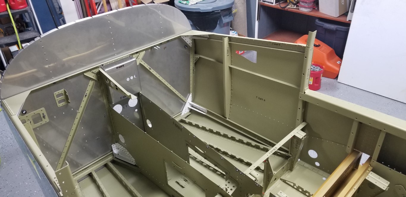


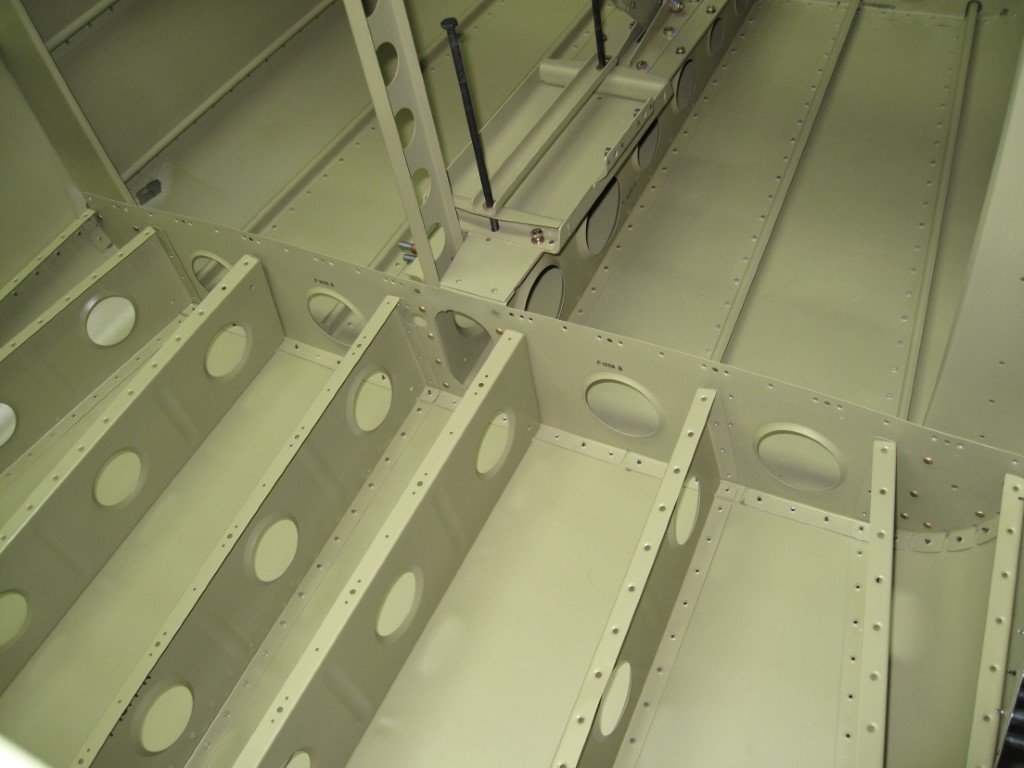
With my Dad’s help, we began riveting the skins to the Bulkhead (F-1006), the Baggage Ribs (F-1019, F-1020, & F-1021), and the Mid Fuselage Longerons (F-1046). We finished up by riveting the Baggage Ribs to the Bulkhead (F-1006B) and installed the two snap bushings (SB625-7).


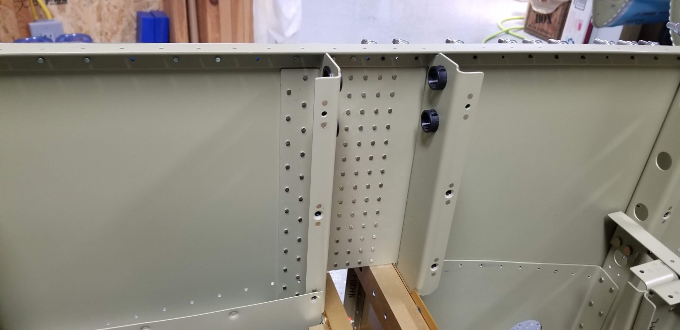
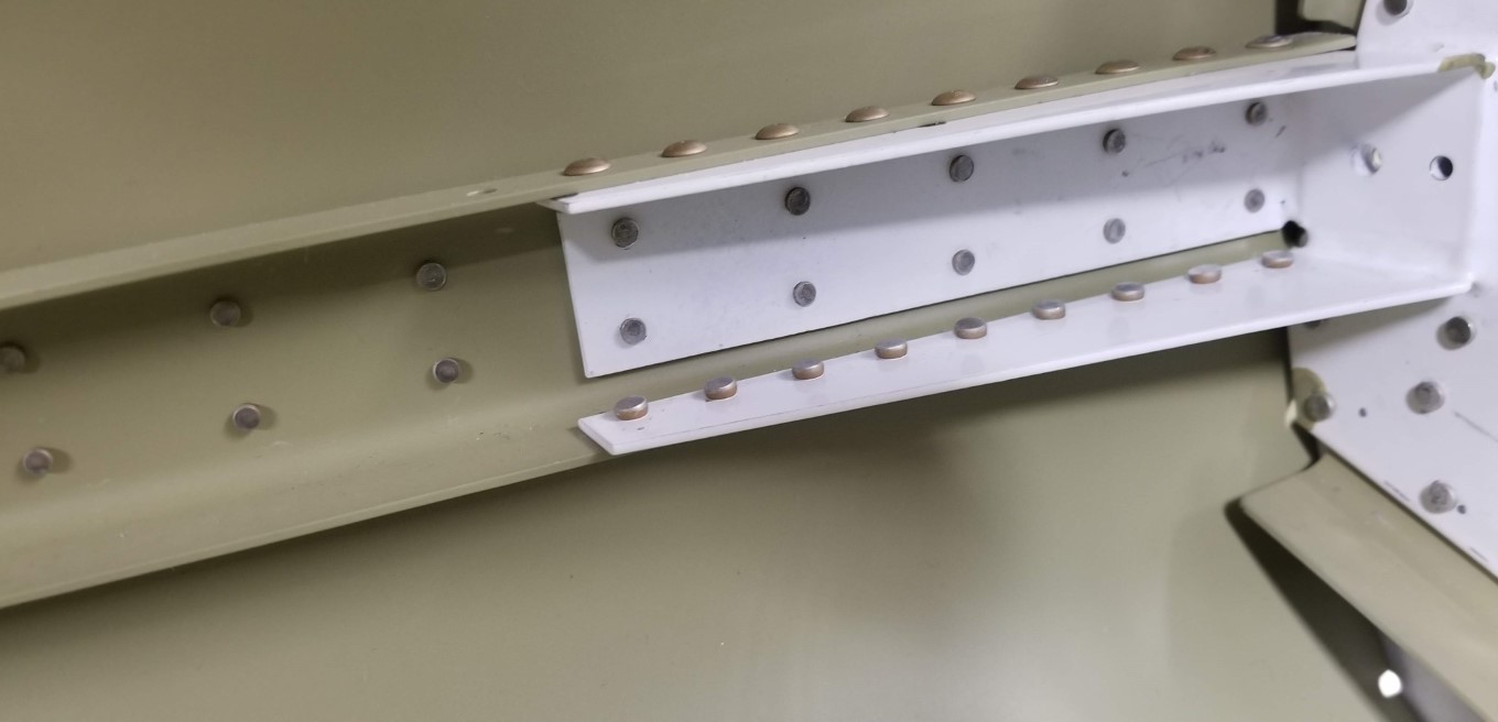
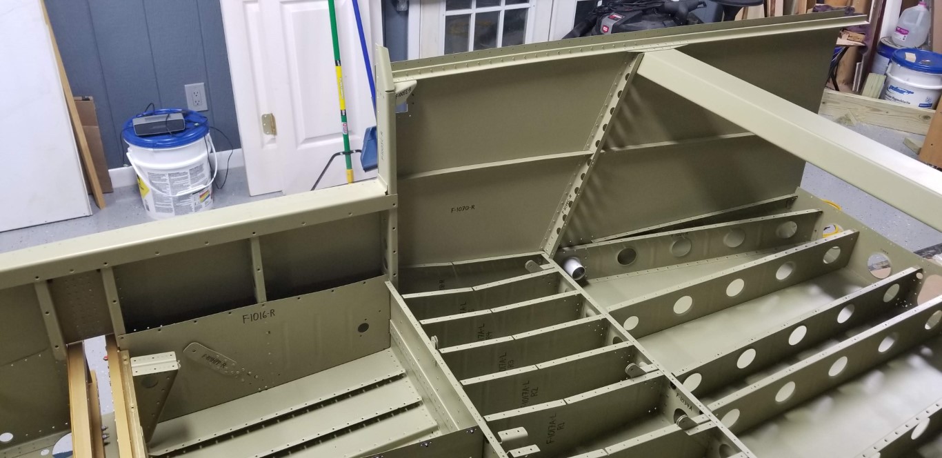
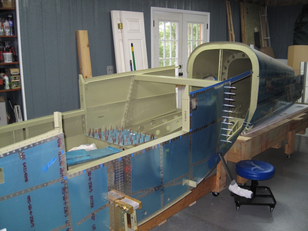
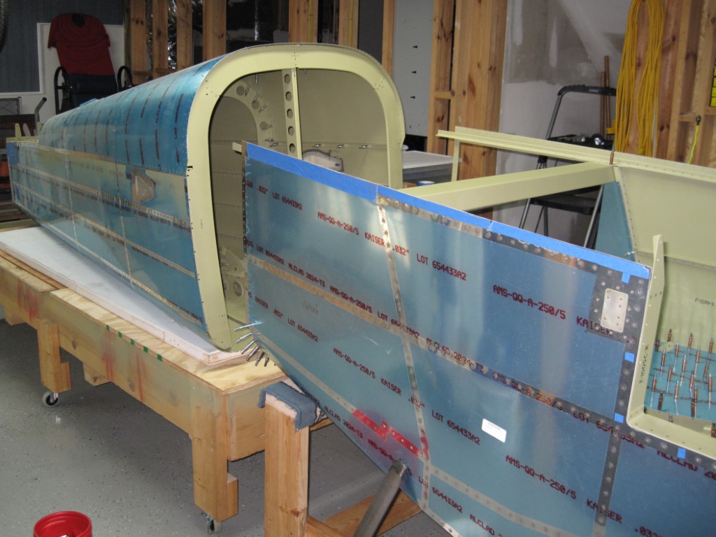
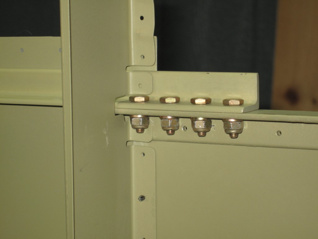
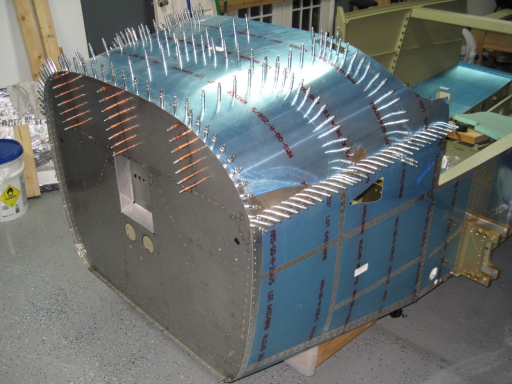
Today was a huge milestone because it was finally time to attach the Tailcone!!! After some preliminary work that was required around the Bulkheads (F-1006), I clecoed the Tailcone Skins to the Mid Fuselage Skins. Next I final-drilled #30 the holes common to the aft flange of the Baggage Ribs and the Bulkhead. Then after I ensured the Mid Fuselage and Tailcone Longerons were aligned, I clamped them together and began match-drilling the four holes with a #30 drill. Next I final-drilled #12 each hole and bolted each one as I drilled. I had to make some shims from a scrap piece of 0.25” aluminum sheet to fit between the Tailcone Forward Top Skin (F-1074) and the aft ends of the Mid Fuselage Longerons (F-1046). I could then cleco the Tailcone Forward Top Skin (F-1074) to the tailcone and match-drill #40 the holes of the Mid Side Skin (F-1070) and the three holes of the Tailcone Forward Top Skin (F-1074) into the Mid Fuselage Longerons (F-1046) and the shims I had made previously. I final-drilled #40 the holes common to all of the skins and the Bulkheads (F-1006) and then removed the Tailcone from the Mid Fuselage. I deburred and dimpled all of the holes that have been drilled during this section before I finally reattached the Tailcone to the Mid Fuselage and then bolted the Mid Fuselage Longerons (F-1046) to the Tailcone Longerons (F-1032).


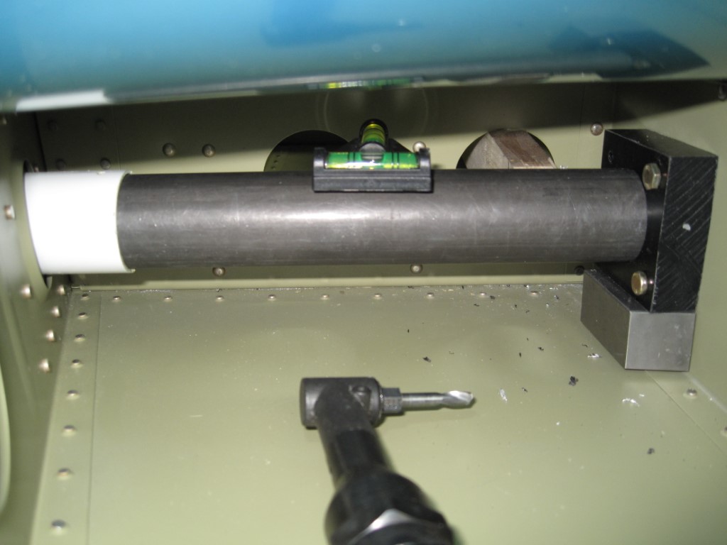
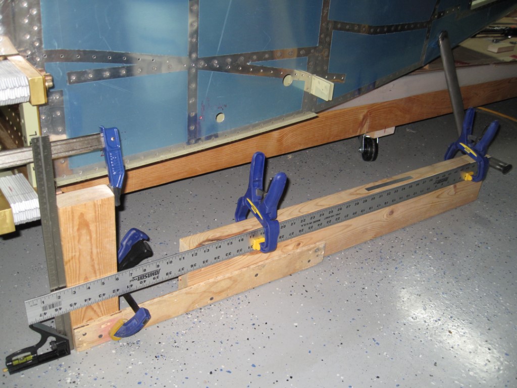
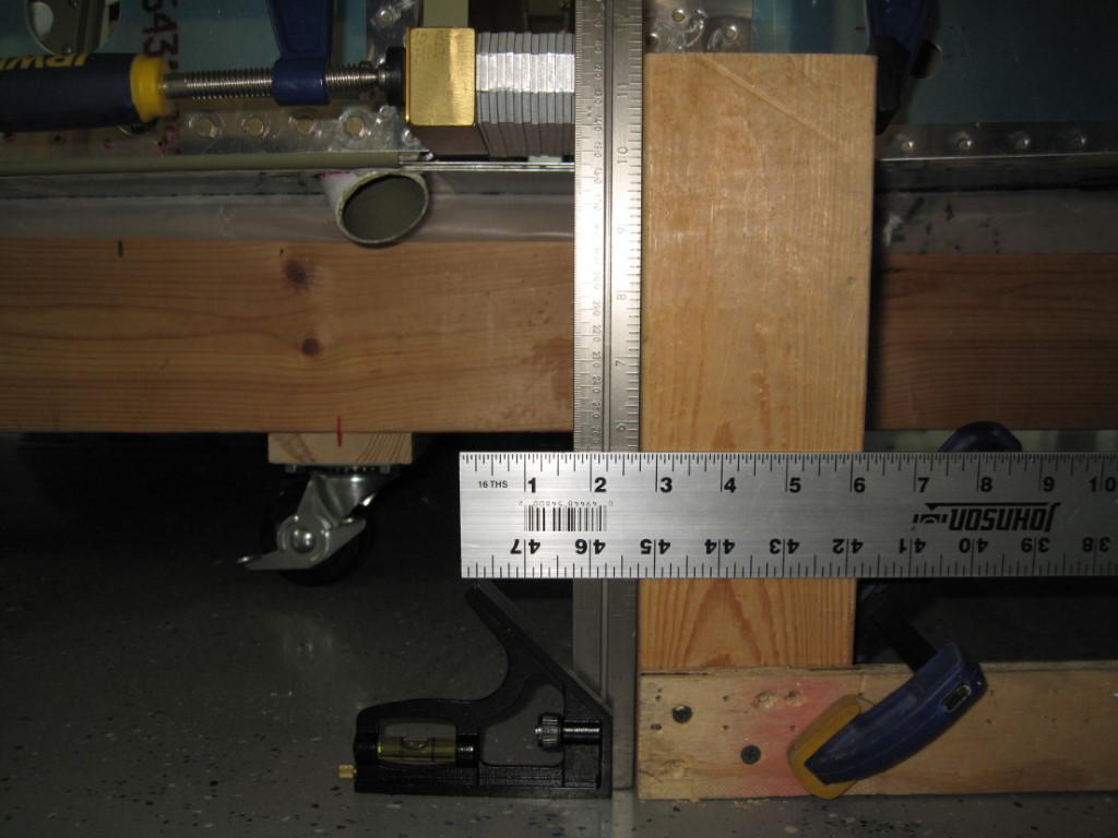
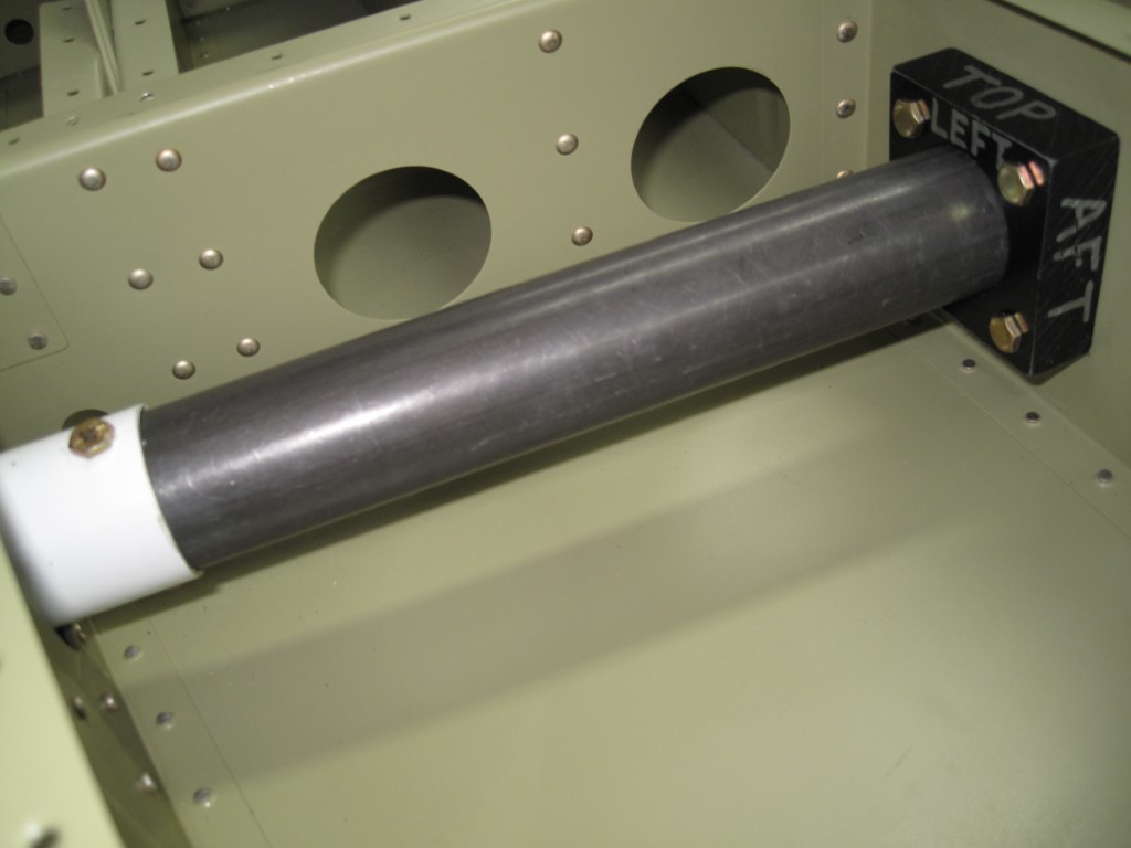
I began working on the Step Installation section by first drilling the four holes in the Step Support Blocks (F-1038) per the dimensions given. I deburred the edges of the Steps (WD-1007) and inserted them into the Step Mounting Brackets (WD-1008). I slipped the Support Blocks (F-1038) over the end of the tubes and then positioned them against the web of the Mid Baggage Ribs (F-1020). I adjusted the position of the Support Blocks per the instructions and then match-drilled #12 two of the pre-drilled holes into the Mid Baggage Ribs (F-1020). I then temporally bolted those holes to the Mid Baggage Ribs, removed the Steps, and match-drill #12 the remaining holes. Next I marked the top, aft, and outboard face of the Support Blocks before I removed them and the Steps from the Mid Baggage Ribs. After deburring the holes in the Mid Baggage Ribs, I bolted the Support Blocks back onto the Mid Baggage Ribs and reinserted the Steps. Now I could began adjusting the position of the Steps by using the 45.25 inches to set the proper sweep angle of both Steps. Once I got the sweep angle set on the Steps, I used the guide hole to match-drill #30 through the Steps and the Step Mounting Brackets. I removed the Steps and deburred the holes before I began installing the Step Support Bushings I bought from TCW. I then reinstalled the Step and the bolt before I clecoed the Baggage Floor (F-1022A) to the fuselage. This way I was able to locate where I will need to install inspection panels in the Baggage Floors so that I will have access to the Step bolt in the future, if needed.


I continued today by positioning the Instrument Panel Attach Flanges (F-1003D & E) simultaneously against the Forward Fuselage Top Skin (F-1071) and the forward side of the Instrument Panel (F-1003A). As I held the attach flanges in place, my Dad match-drilled #40 the holes by using the Forward Fuselage Top Skin as the drill guide. Afterwards I match-drilled #19 through the screw holes in the Instrument Panel (F-1003A) into the Instrument Panel Attach Flanges (F-1003D & E). I then proceeded to remove the Instrument Panel Attach Flanges (F-1003D & E) and then using a nutplate as a drill guide, I match-drilled #40 the two nutplate attach holes for each screw hole. I deburred the holes and edges of the Instrument Panel Attach Flanges before I dimpled the nutplate attach holes and the skin attach holes. Next I machine countersunk the rivet holes in the Hand Hold Doublers and then removed them from the Forward Fuselage Top Skin (F-1071) and deburred the holes and edges. I removed the Forward Fuselage Top Skin (F-1071) from the sub-structure and deburred the holes and edges. I then dimpled all the holes except those that had been marked. I also deburred and dimpled the holes in the flanges of the Firewall Bulkhead (F-1001A) that are common to the Forward Fuselage Top Skin (F-1071). I removed the Instrument Panel subassembly from the Forward Fuselage Ribs (F-1044A & F-1045) and disassembled the Instrument Panel Attach Flanges and Instrument Panel Lower Flange from the Instrument Panel. I deburred all the holes and edges of the Instrument Panel Attach Flanges and then dimpled all the rivet holes as was required. I removed the Sub-Panel / Forward Fuselage Rib Subassembly from the Forward Fuselage, disassembled it into its individual components, and then deburred the holes and edges of all the parts. Finally I dimpled the skin attach rivet holes in the Forward Fuselage Ribs (F-1044A & F-1045), Sub Panel Center (F-1068A), and Sub Panel Sides (F-1068).


Today I began attaching the Instrument Panel Lower Flange (F-1003B) and Instrument Panel Attach Flanges (F-1003C) to the Instrument Panel (F-1003A). I positioned the Instrument Panel Attach Flanges (F-1003D & E) over the Instrument Panel and fluted the outboard ends as I needed to match the Instrument Panel upper edge contour. I then attached the Instrument Panel subassembly to the Forward Fuselage Ribs (F-1044A & F-1045) and clecoed the Forward Fuselage Top Skin (F-1071) to the Instrument Panel understructure. Next I had to form the Hand Hold Doublers (F-1071B) to match the contour of the Forward Fuselage Top Skin (F-1071), which created a left and right hand version of the Hand Hold Doublers. I then clecoed the Hand Hold Doublers to the Forward Fuselage Top Skin and final-drilled #40 all the holes that are common between the two parts. I also traced the perimeter of each Hand Hold Doubler so that I know which holes will not be dimpled in the Forward Fuselage Top Skin (F-1071) and final-drilled #40 all the holes in the top skin that are common to the sub-structure.


Tonight I began cutting the four Spacers (F-1082) from the tubing that was provided to a length of 1.6875” to 1.7031”. This took some time to accomplish as I repeatedly checked each one with my calipers to ensure I was within tolerance. Next I installed the Landing Gear Mount (WD-1021-PC) by bolting them to the Center Section (F-1004), Shim (WD-1021P), Center Section Side Plate (F-1004K), Forward Side Skin (F-1069), Forward Floor Panel (F-1050), and the Forward Fuselage Floor Rib (F-1049C) using the hardware that was specified.


I wanted to get the Vent Doors installed next, therefore I began riveting the Vent Doublers (F-1096) and the Vent Brackets (F-1086A&B) to the Mid Side Skin (F-1070). Next I riveted the Vent Slides (F-1087A&B), Vent Door Doublers (F-1092), and the Vent Doors (F-1093) together per the instructions. I then inserted the Vent Door Subassembly and installed the hardware through the Vent Brackets (F-1086A&B) and the slot in the Vent Door Subassembly.


I spent today installing the Forward Cabin Floor Panels (F-1050) into the fuselage by inserting the forward inboard corners beneath the Nose Gear Tension Fitting (WD-1004) and then slid the forward edges beneath the Firewall Lower Channel (F-100C). I lowered the aft end of the forward cabin floor panel into place and clecoed the forward cabin floor panel to the mating structures. Finally I blind riveted the Forward Cabin Floor Panels into place using the LP4-3 and CS4-4 blind rivets.


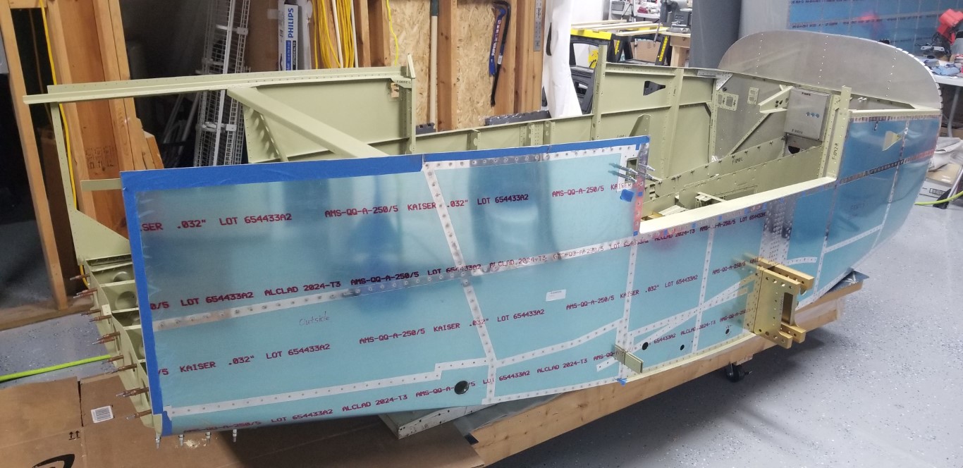
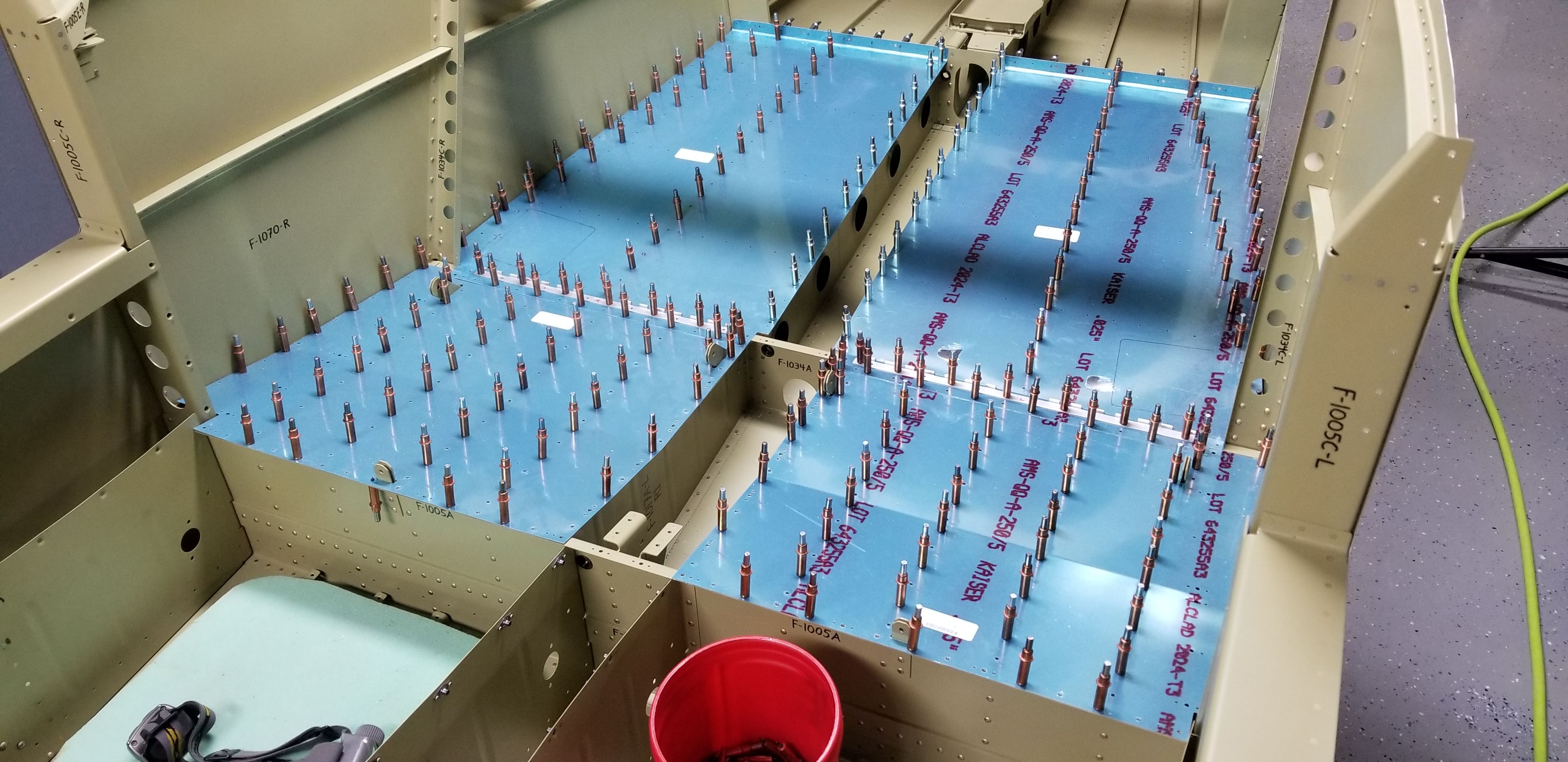
Over the course of a few weeks, my Dad and I began riveting the Fuselage Side Skins together. We started off by riveting the double row of rivets on either side of the joint between the Forward Side Skins (F-1069) and the Mid Side Skins (F-1070). Next we riveted the Mid Side Skins (F-1070) and the Forward Side Skins (F-1069) to the fuselage assembly understructure. I then clecoed the Mid Cabin Decks (F-1015C) to the understructure and we began riveting it to the Bulkhead Side Channels (F-1005C), Foot Well Rib Intercostals (F-1015B), the other Bulkhead Side Channels (F-1042), and the Forward Fuselage Longerons (F-1013). Finally we clecoed and riveted the Forward Fuselage Ribs (F-1088) to the Forward Fuselage Bulkheads (F-1002), the Bulkhead Side Channels (F-1042), and the Forward Side Skins (F-1069).